AI Assistant
Full AI integration directly inside Siemens Process Simulate for engineering automation, simulation assistance, offline programming and virtual commissioning workflows.
Solutions for simulation, virtual commissioning, connectivity, AI integration and manufacturing workflows. Every solution shown here can be implemented in your Process Simulate environment as an engineering service — adapted, integrated, tested and handed over by the engineer who developed it.
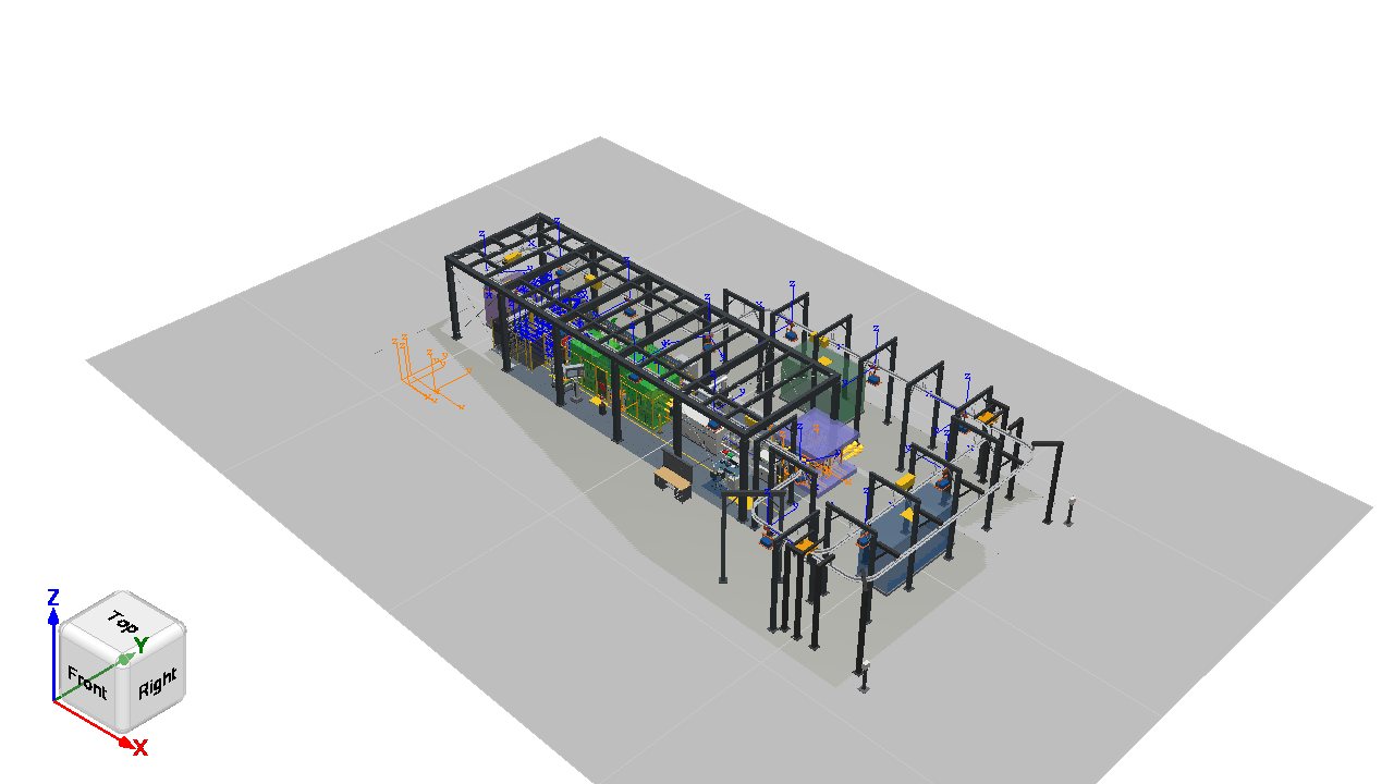
The cell above is a real study, exported from Process Simulate with our own GLB exporter. Rotate, zoom, select objects and play the simulation.
Every capability in this portfolio is available to you as an engineering service. There is no software shop: you commission the implementation, and the solution is adapted to your environment, integrated, tested and handed over as a customer-specific project.

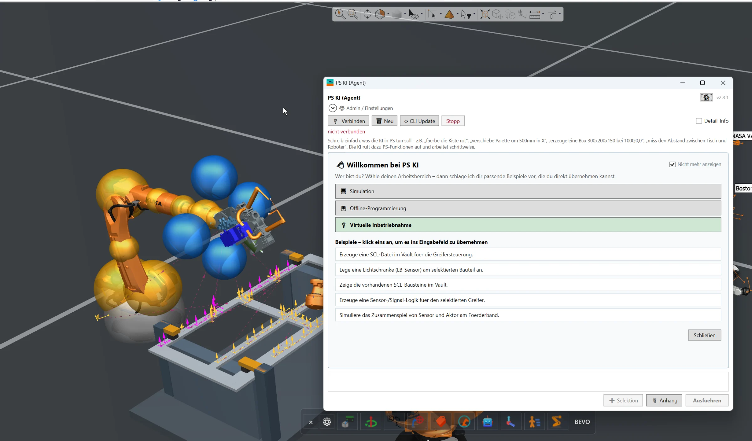
Full AI integration directly inside Siemens Process Simulate for engineering automation, simulation assistance, offline programming and virtual commissioning workflows.

Complete humanoid engineering workflow for Siemens Process Simulate, including URDF import, walk-path definition, task-oriented programming, reachability analysis, collision-free motion planning and NVIDIA HALOS-based safety validation concepts.

MQTT connectivity directly inside Siemens Process Simulate for exchanging simulation data, machine states, events and project information with external systems and applications.

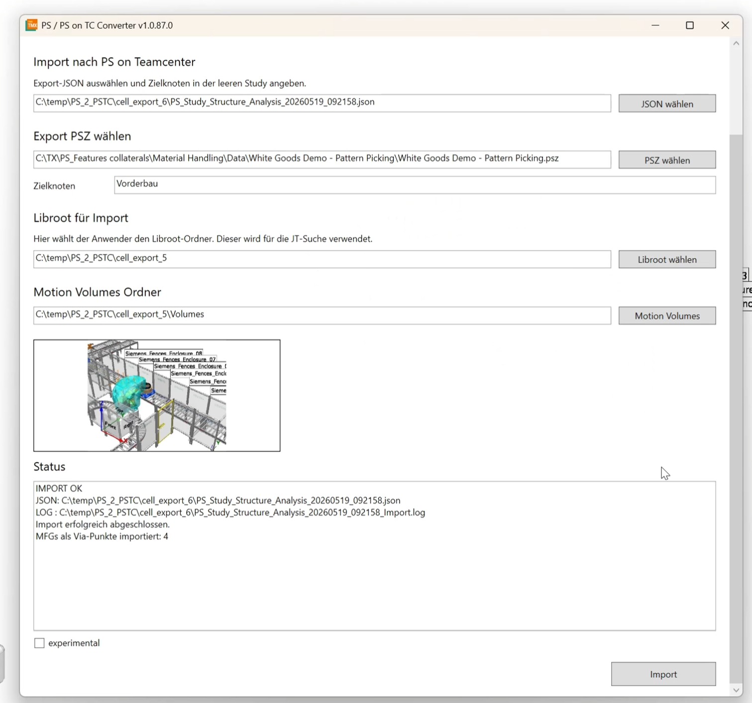
Automated conversion of existing Process Simulate Standalone, PSZ and EMS cell structures into Process Simulate in Teamcenter, including geometry, kinematics, robot paths, motion volumes, classes and object types.

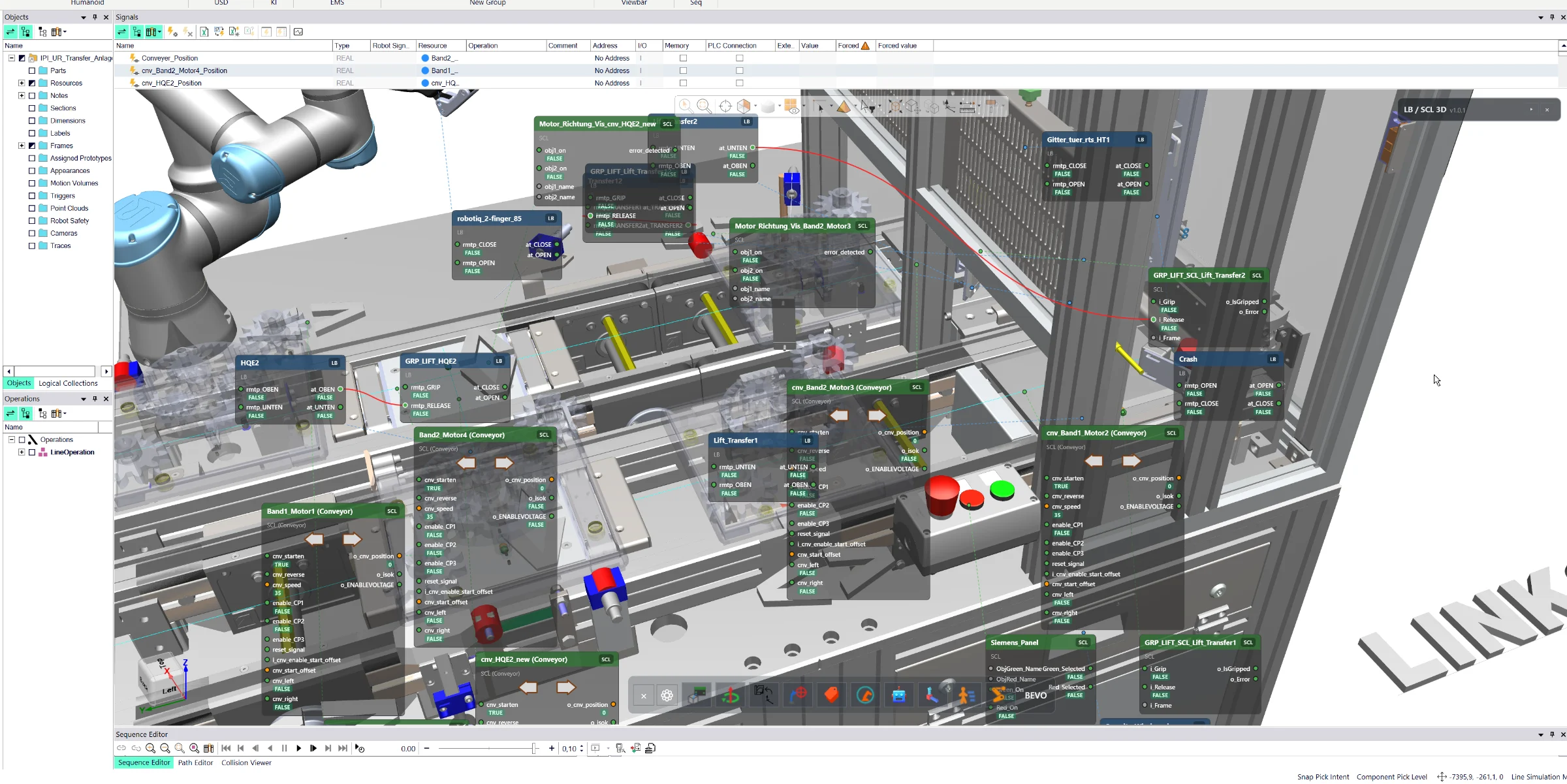
Interactive 3D visualization of logic blocks, signal connections and live machine states directly inside Siemens Process Simulate for faster virtual commissioning and debugging.

Advanced OPC UA connectivity for Siemens Process Simulate with secure authentication, certificate handling and access to local, network-based and cloud-connected OPC UA servers.

Direct joint manipulation inside the Siemens Process Simulate 3D environment for robots, resources and conveyors — without opening additional joint control windows.

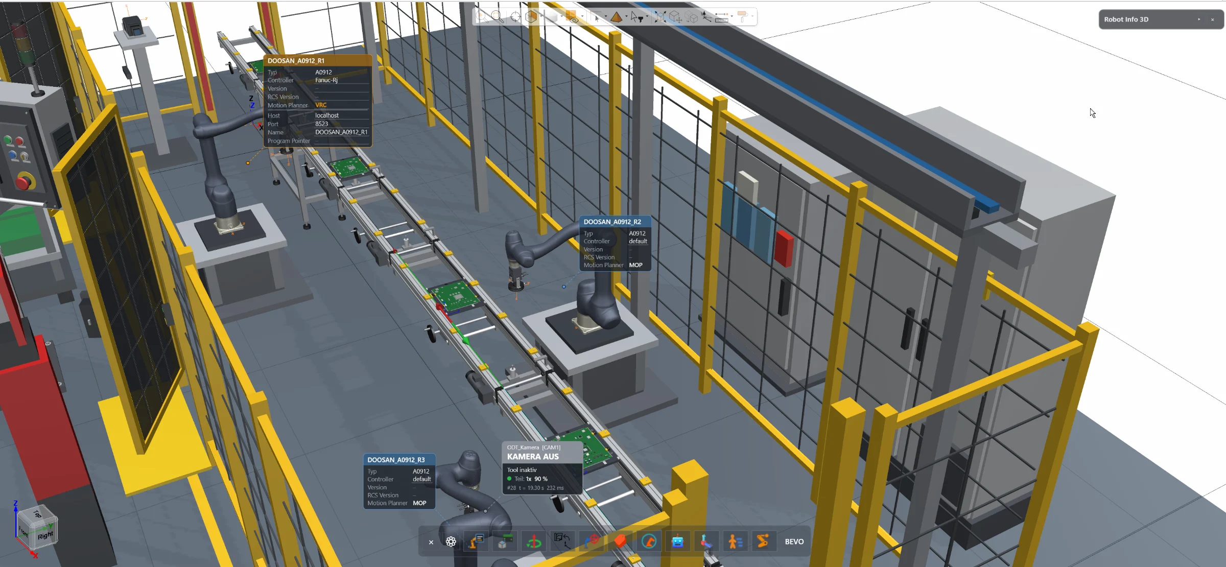
Access essential robot information and configuration directly inside the Siemens Process Simulate 3D environment — without opening the separate Robot Center window.

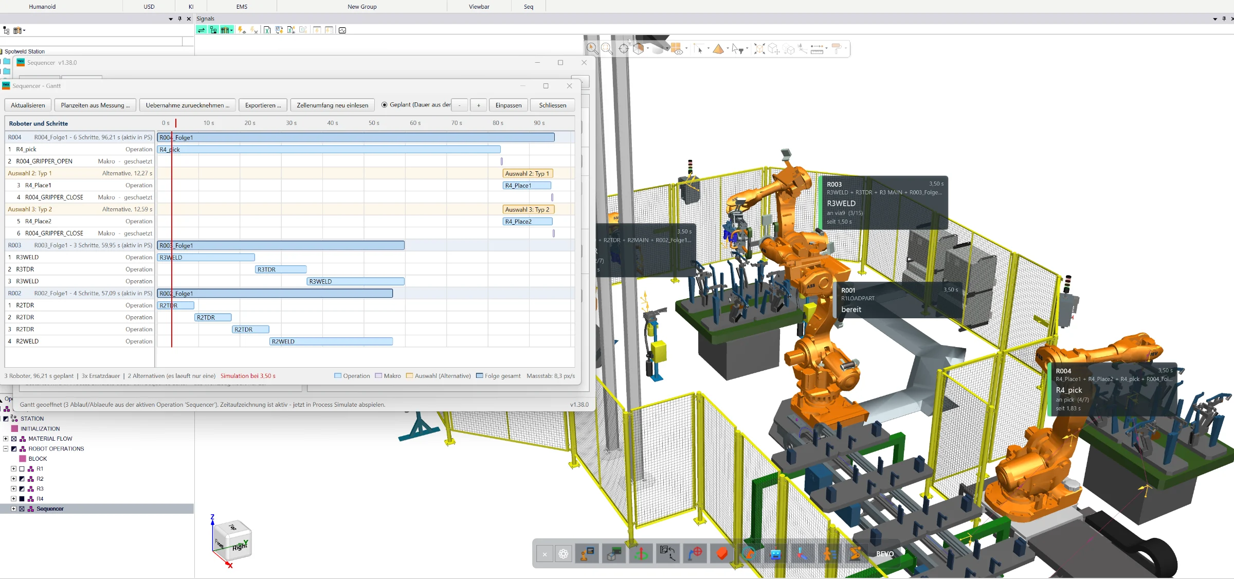
Create, simulate and optimize complete manufacturing sequences directly in Siemens Process Simulate Standard Mode — with wizard-based program generation, collision analysis, robot interlocks, 3D visualization and Gantt-based cycle-time optimization.

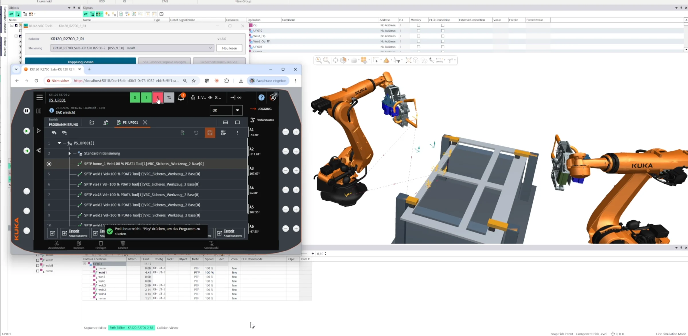
Direct connection between Siemens Process Simulate and the KUKA Virtual Robot Controller without additional configuration tools. Use KUKA VRC directly in Standard Mode or Line Simulation, exchange robot and safety signals, visualize safety zones and transfer robot operations and locations directly from Process Simulate.

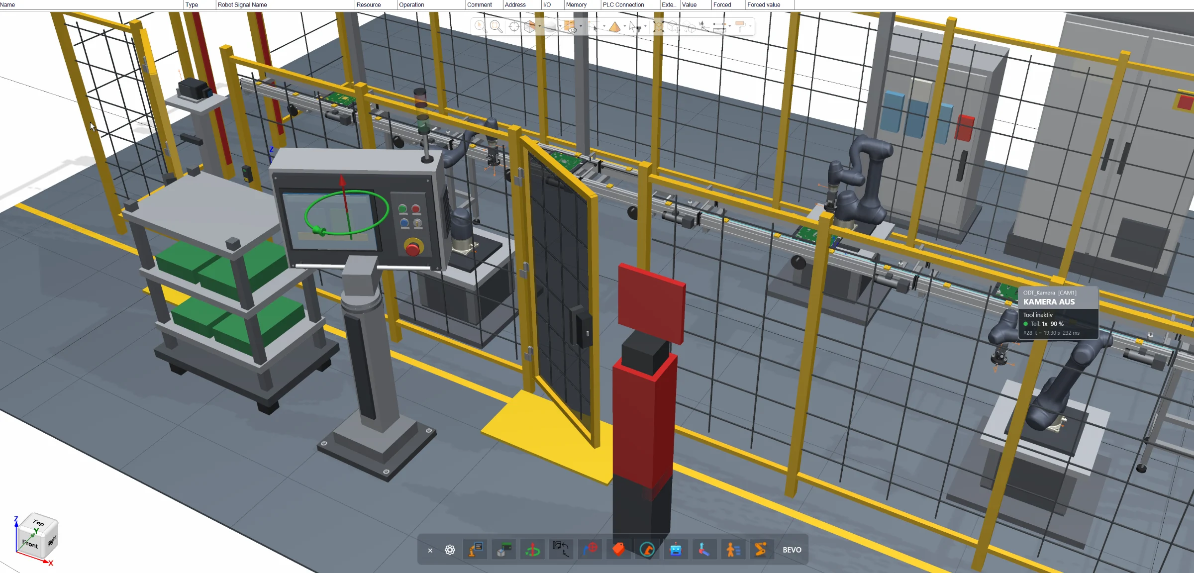
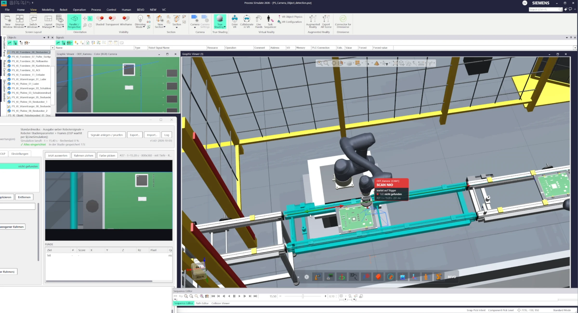
Configurable vision camera for Siemens Process Simulate that detects and evaluates objects directly in Standard Mode or Line Simulation. Configure image, color, contour or other detection criteria, trigger inspections and return the resulting signals directly to the simulation logic.

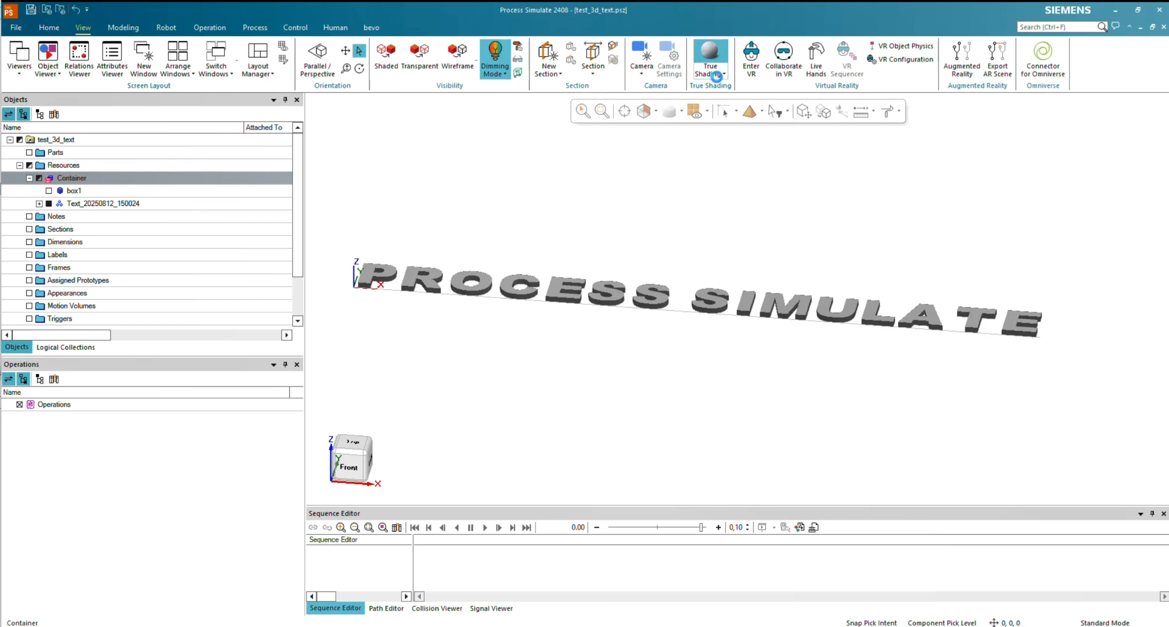
Create 3D text directly inside Siemens Process Simulate. Enter any text, define its size and 3D dimensions, and the tool automatically generates the corresponding geometry using the built-in modeling functionality.

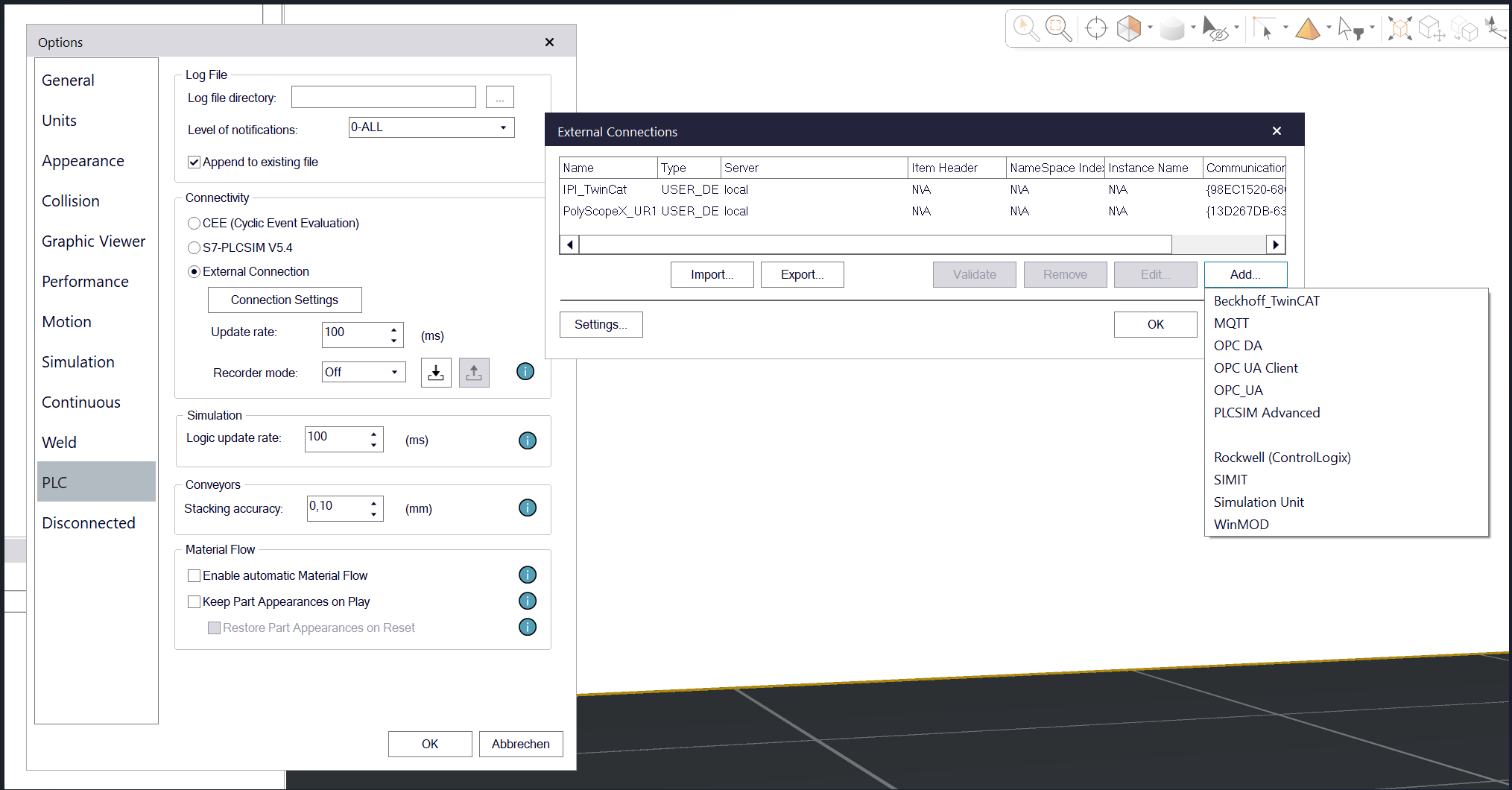
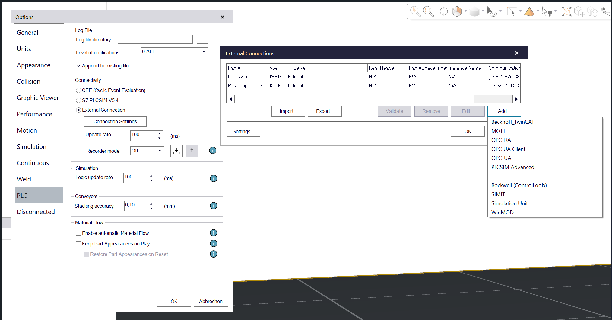
Connect Siemens Process Simulate directly to Universal Robots virtual controllers running PolyScope 5 or PolyScope X. Native, bidirectional VRC integration in Standard Mode and Line Simulation Mode – no additional installation or configuration required. Transfer robot operations, teach points and exchange controller data with just one click.

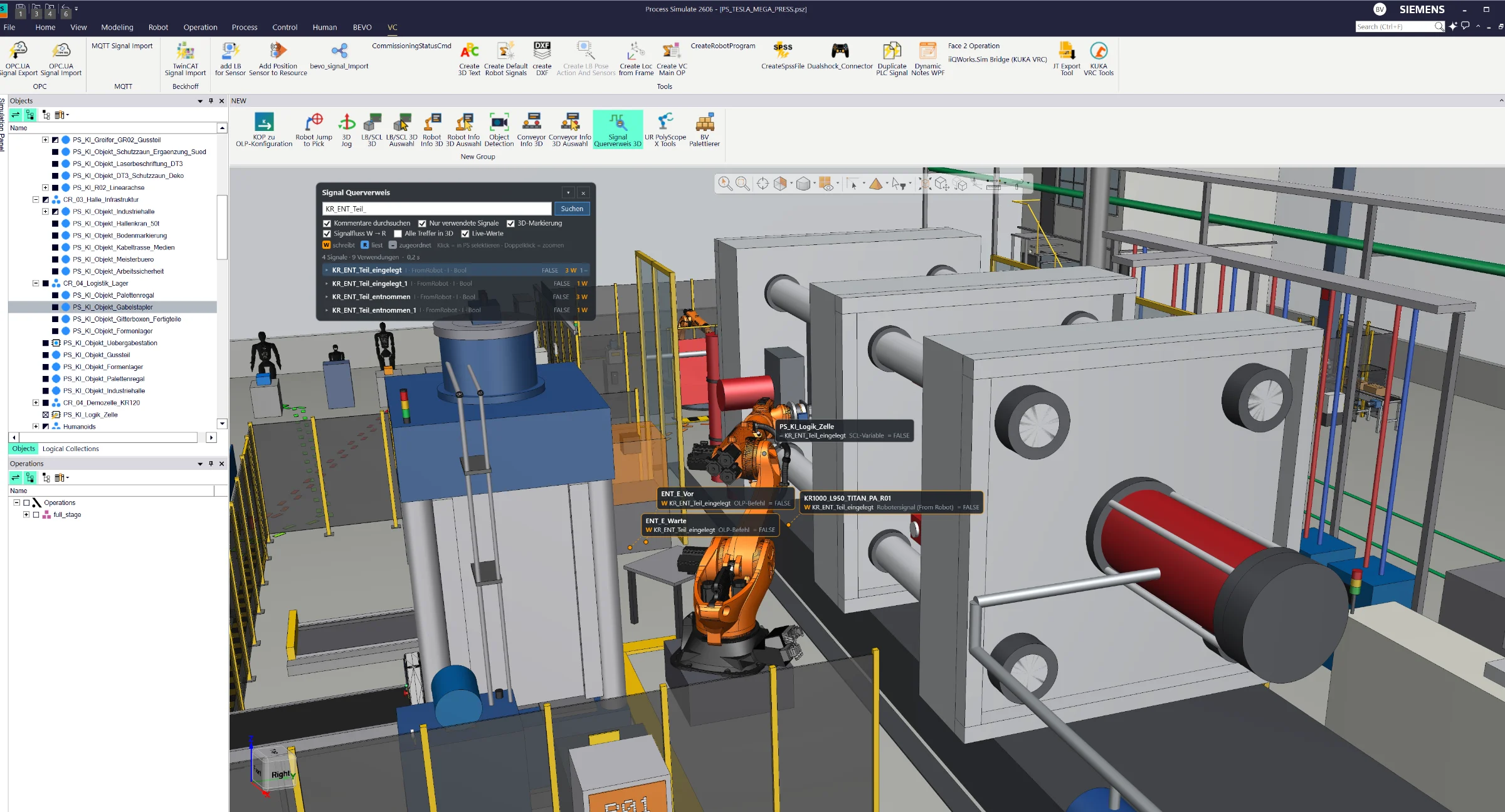
Find every signal and its usage across your entire Process Simulate cell. Instantly locate references in logic blocks, modules and OLP commands, visualize signal locations in 3D and monitor live signal states in Line Simulation Mode – all through an intuitive on-screen tool.

Visualize conveyor properties, control points, stop points and live status information directly in the Siemens Process Simulate 3D Viewer. Color-coded indicators provide instant insight into conveyor behavior, object positions and material flow.

Visualize logic blocks, SCL blocks, signals and their connections directly in the Siemens Process Simulate 3D Viewer. Trace logical relationships through 3D connection lines and monitor live signal states, color-coded connections and conveyor directions in Line Simulation Mode.

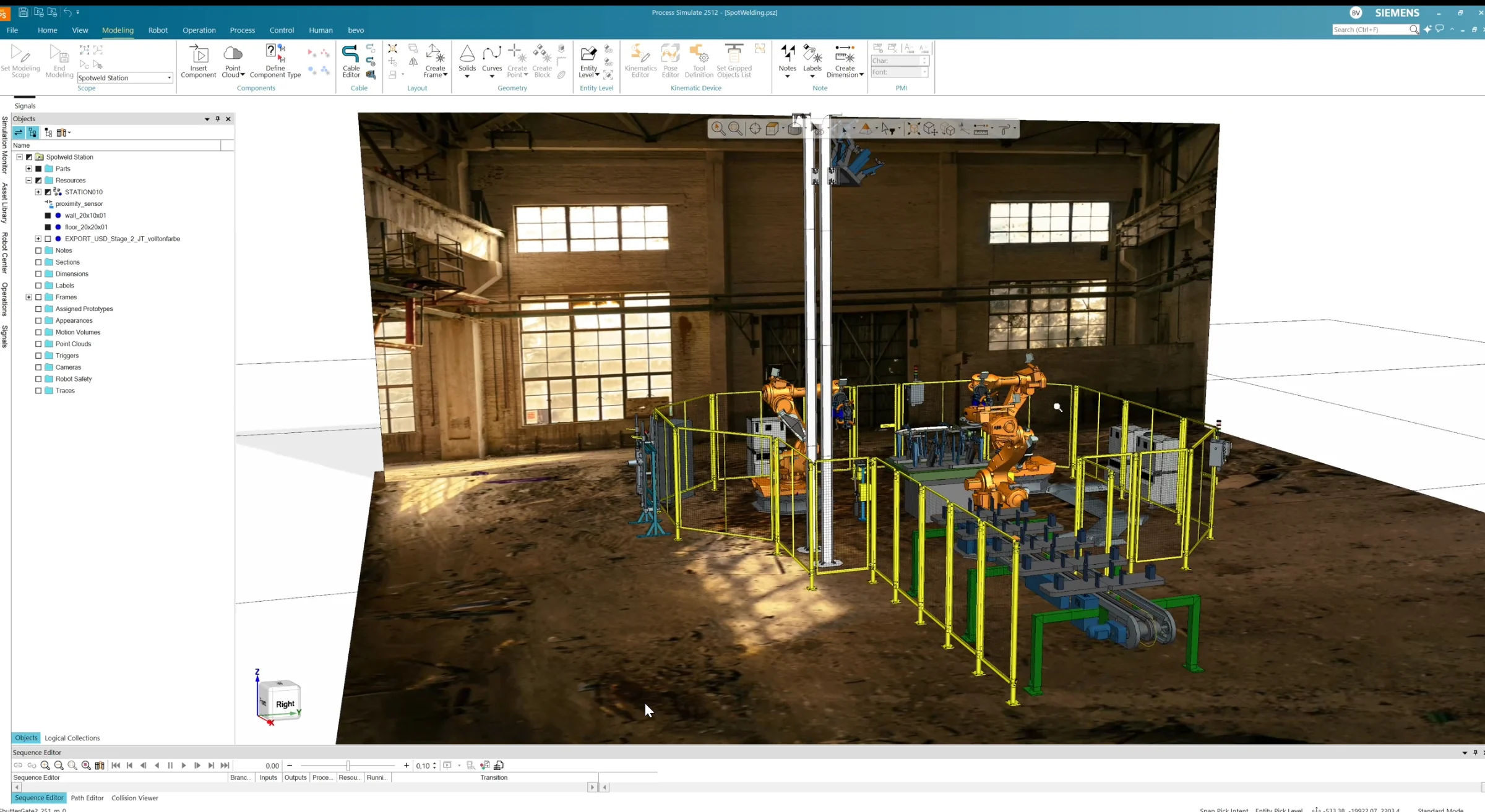
Bring realistic textures into Siemens Process Simulate using standard JT files. Create textured JT models through a dedicated user workflow and import them directly into your simulation – without Vis Mockup or additional specialized software. Transform neutral CAD geometry into visually realistic 3D environments.

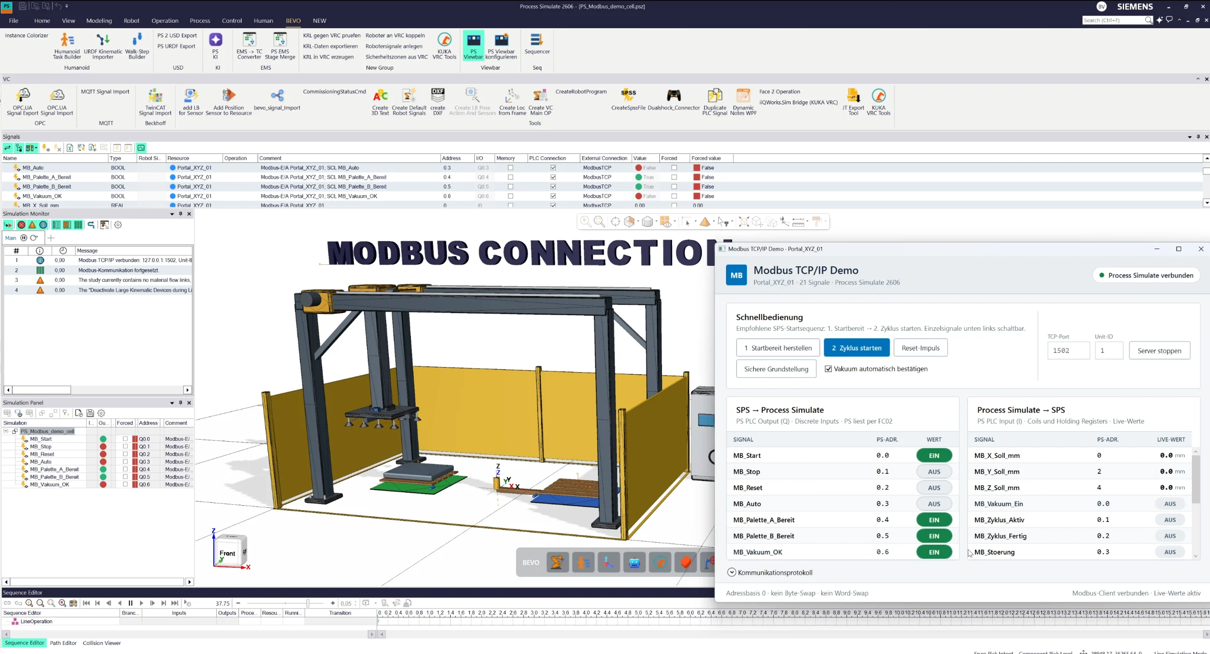
Connect Siemens Process Simulate directly to Modbus TCP/IP controllers and PLCs. Exchange input and output signals in real time and use them directly within Process Simulate for control logic, equipment simulation and virtual commissioning.
Every implementation starts with the customer’s actual Process Simulate setup, required modules, interfaces and workflow. Scope, integration and testing are defined as an engineering project — not as a generic software download.
The commercial model is transparent: you request a solution, we define the technical scope, and you commission the implementation as an engineering service. At the end, the solution runs in your environment.
Choose the solutions you need and send a short, non-binding inquiry.
Clarify Process Simulate version, modules, interfaces and workflow. You receive a defined engineering scope and quotation.
The solution is adapted and integrated into your environment as a dedicated engineering service.
Testing, handover, documentation and support — then you work with the solution in production.
Technical demonstrations, development concepts and experiments are published on the Benjamin Völzke YouTube channel.
Create 3D text directly inside Siemens Process Simulate. Enter any text, define its size and 3D dimensions, and the tool automatically generates the corresponding geometry using the built-in modeling functionality.
3D Text Generator extends the modeling capabilities of Siemens Process Simulate with a simple workflow for creating text directly as 3D geometry.
Instead of modeling text externally or importing prepared CAD geometry, users simply enter the required text and define parameters such as size and 3D depth.
The extension automatically uses the available Process Simulate modeling functionality in the background to generate the corresponding 3D text and place it directly into the current simulation cell.
This is especially useful for creating labels, machine names, station identifiers, safety markings, process information or other visual annotations directly inside the 3D environment.
The tool reduces manual modeling effort and provides a fast way to enrich simulation cells with readable 3D information.
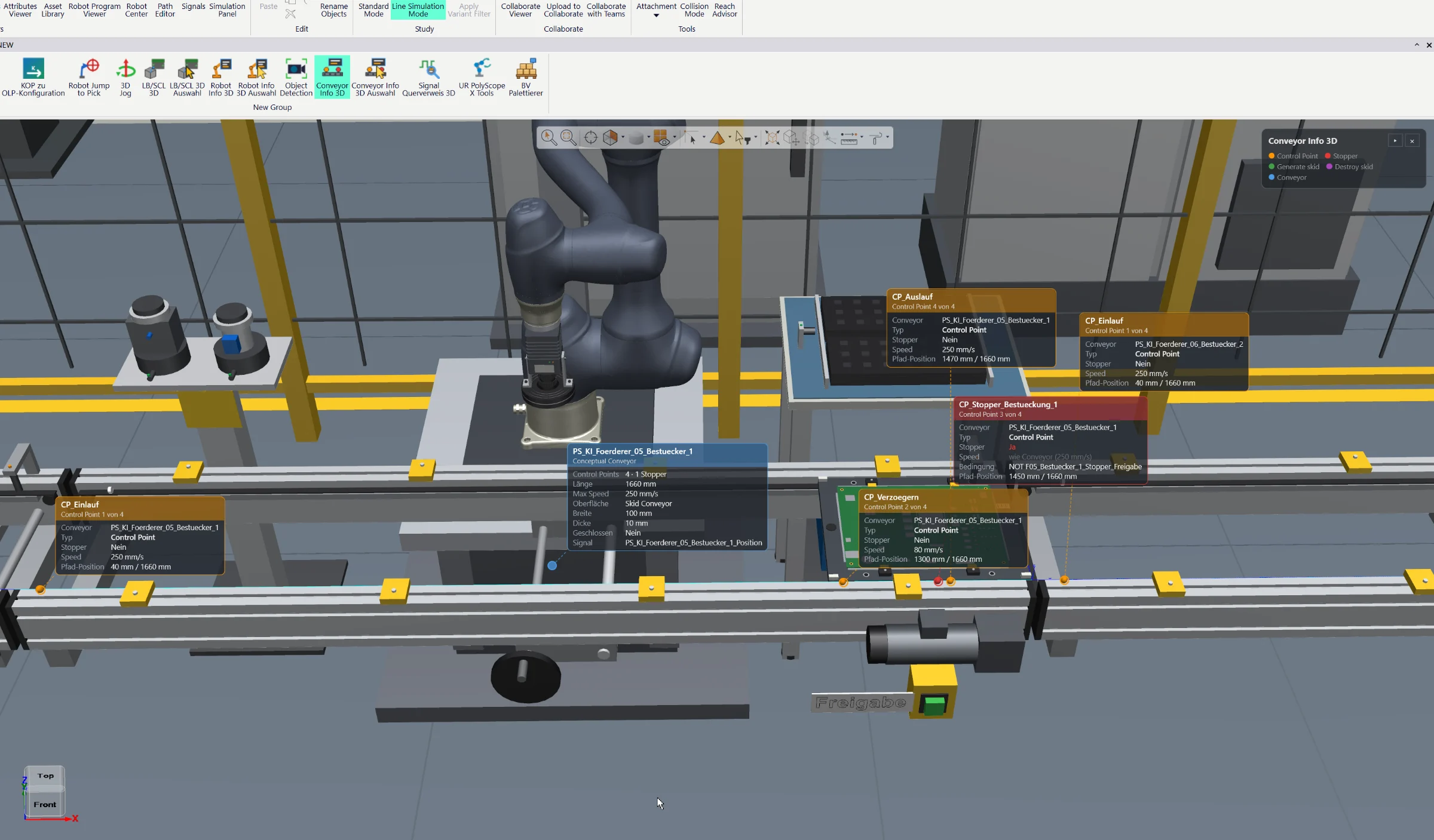
Visualize conveyor properties, control points, stop points and live status information directly in the Siemens Process Simulate 3D Viewer. Color-coded indicators provide instant insight into conveyor behavior, object positions and material flow.
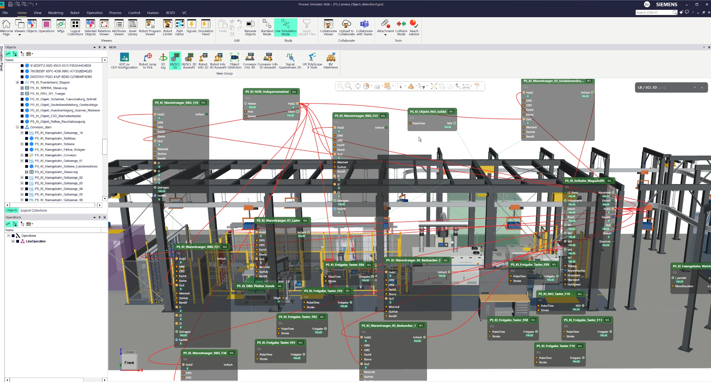
Visualize logic blocks, SCL blocks, signals and their connections directly in the Siemens Process Simulate 3D Viewer. Trace logical relationships through 3D connection lines and monitor live signal states, color-coded connections and conveyor directions in Line Simulation Mode.

Full AI integration directly inside Siemens Process Simulate for engineering automation, simulation assistance, offline programming and virtual commissioning workflows.
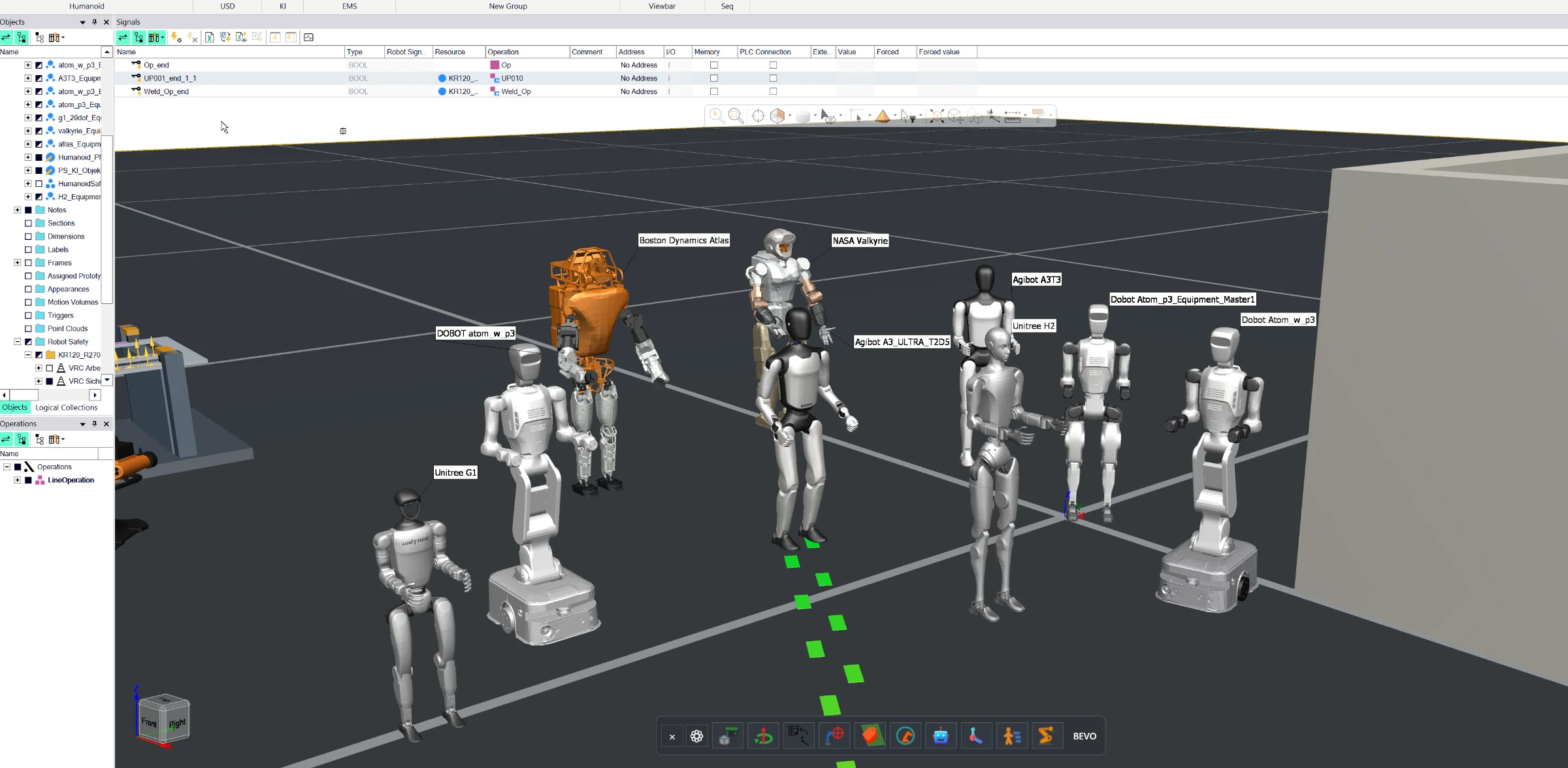
On the BV marketplace for NVIDIA Kit / USD Composer.
Tell us which solution you are interested in and how your Process Simulate environment is set up. The request becomes the starting point for a customer-specific engineering scope.
Every solution shown on this website is provided as an engineering service. After your request, the implementation scope, required interfaces, customer environment and commercial terms are defined individually — then the solution is implemented, tested and handed over in your environment.